208 Rock Blasting
General Information
This section only covers the
basic concepts of rock blasting. The
topic is covered in more detail in the FHWA manual, Rock Blasting and Overbreak Control,
FHWA-HI-92-001. Many of the figures and specification concepts originated from
this manual. The manual is available on
the FHWA website:
http://www.fhwa.dot.gov/engineering/geotech/library_listing.cfm
There used to be a training
course from NHI for Rock Blasting and Overbreak Control, but unfortunately this course is no
longer available from NHI.
Rock Blasting Basics
Rock blasting consists of
drilling holes in the rock at depths, in diameters, and at spacing so that the ANFO, which is a mixture of Ammonium Nitrate (fertilizer)
and Fuel Oil (diesel fuel), can fracture the rock in a controlled manner. The rock must fracture enough to displace it
and break it down to the size of the intended use.
The specifications limit the
way blasting contractors can blast to ensure that rock or blast vibrations do
not harm people or adjacent property.
Blasting Free Body Diagram
The basic geometry for rock
blasting is shown in Figure 208.A.
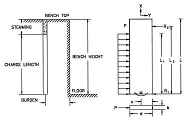
Figure
208.A – Rock Blasting Free Body Diagram
Holes are drilled to the
required depth in order to remove the rock and then filled with ANFO (the charge length).
The charge is topped off with stemming, which helps to hold the blast
down. The free body diagram on the
right-hand side of Figure 208.A shows the explosive pressure (P) and moment (M)
from the blast.
The blaster and blasting
consultant can arrange the geometry of the blast for optimal breakage. This is done so that P and M do not exceed
the amount needed to break the rock.
Excessive P and M causes flyrock and excessive
air blast and vibrations, which can cause damage and injury.
Blasting Geometry and Symbols
Figure 208.B further defines
the rock blasting geometry.
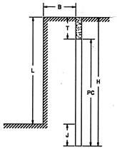
Figure
208.B – Rock Blasting Geometry and Symbols
Figure 208.B illustrates the
following blast geometry parameters:
§ B (Burden) is the distance between the free face and
the first hole.
§ T is the stemming (the inert material in the hole).
§ L is the length of the bench height.
§ H is the blasthole depth.
§ PC is the powder column length (ANFO).
§ J is the subdrill depth or
the depth the hole extends below the planned cut.
Two main parameters to
remember here are the L/B ratio and the stemming height.
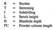
Hole Spacing and Timing
The top view of the rock
blasting geometry is shown in Figure 208.C.
Notice the distance B is still the distance to the free face. The distance S, or spacing of the holes, is a
function of the burden.
Figure
208.C – Rock Blasting (Top View)
The spacing of the holes and
the timing (or delay) of the holes are part of the blasting design. The bottom illustration in Figure 208.C shows
how the blast is delayed by the sequencing numbers. Each hole may be blasted milliseconds apart
to control the blast. The row-to-row
shots are certainly time delayed.
An initiation system
transfers the detonation signal from hole-to-hole at precise times. Plastic
shock tubes or electric caps using a timing system are generally employed. A shock tube is non-electric, instantaneous,
and has a thin reactive powder that propagates the shock wave signal.
The timing or delay minimizes
the pounds of explosive per delay period. This can significantly control noise
and vibration effects. It would be a
disaster if all the holes went off at the same time.
The design variables of
burden, stemming, subdrill length, spacing, and
timing are selected to maximize fragmentation and to minimize excessive
vibration, air blast, and flyrock.
Effects of L/B Ratio
Figure 208.D shows what happens
when the ratio between the distance L (bench height) and B (burden) is
changed. Potential blasting problems are
decreased as the ratio is increased. As
this ratio is decreased, these problems are increased.
|
Stiffness
Ratio (L/B) |
1 |
2 |
3 |
4 |
|
Fragmentation |
Poor |
Fair |
Good |
Excellent |
|
Air
Blast |
Severe |
Fair |
Good |
Excellent |
|
Flyrock |
Severe |
Fair |
Good |
Excellent |
|
Ground
Vibration |
Severe |
Fair |
Good |
Excellent |
|
Comments |
Severe
backbreak and toe problems. Do not shoot. REDESIGN! |
Redesign
if possible. |
Good
control and fragmentation |
No
increased benefit by increasing stiffness ratio above 4. |
Figure
208.D – Potential Problems as it Relates to Stiffness Ratio L/B
The specifications in 208.06.C
require that this ratio be greater than one.
The blasting contractor designs the correct timing, hole
spacing, and stemming. Historically, blasters in Ohio have not had problems
with designs having an L/B ratio near one.
Local blasters are very familiar with local geology as well.
Generally, a ratio near one
maximizes the rock blasting production.
The main problem with designing a ratio near one is that the rock
generally fractures in large chunks.
This can pose problems for the Contractors when trying to use the
material for fill. When the ratio is
increased, it can decrease the particle size of the rock. This allows the material to easily be used as
fill.
Proper Burden
In order to ensure that the
blaster is using the proper burden, follow this rule of thumb: the burden is
usually 24 to 30 times the production hole diameter. For example:
If the production holes have a
diameter of 6 inches (0.5 feet), then the burden should be:
24 × 0.5 ft
= 12 ft
or 30 × 0.5 ft = 15 ft
The burden for the shot
should be between 12 and 15 feet.
Effects of Stemming
The specifications in 208.06.E
require that the stemming depth (T) of inert material be at least 0.7 times the
burden (B). This helps control the air
blast.
Figure 208.E depicts the
effects of stemming. If effective, the
blast direction is lateral. If the stemming is ineffective, the blast can
blow upward and cause excessive air blast. Notice in the poor example, the
blast cuts back into the cut slope. This
is an obvious problem.
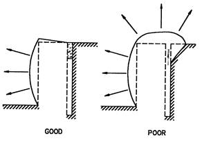
Figure
208.E – Stemming Effects
Drill cuttings are normally
used for stemming. However, when
blasting in water-filled production holes or when blasting within 200 feet of a
structure, the stemming material is changed to prevent problems. For holes less than 4 inches in diameter,
crushed No. 8 stone is required. For
holes 4 inches in diameter or larger, No. 57 stone is required. This helps to hold the blast down better.
Effects of Timing
Timing of the blast is
another important parameter. Figure
208.F depicts the effects of poor and good timing.
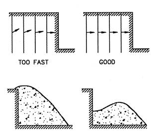
With correct timing, the blast
has a distinct lateral movement. With
poor timing, the movement is more upright and has potential problems.
Vibration and Air Blast Monitoring (208.15 and 208.16)
The blaster is required to
design the burden, stemming, subdrill length,
spacing, and timing to minimize excessive vibration, air blast, and flyrock. The blaster
must monitor the air blast and vibration for every shot at the nearest
structure. Seismographs are used to
monitor the vibration.
Specialized equipment is used
to monitor the air blast. The maximum
air blast, in 208.16.A,
is required to be under 134 dB. The air blast limit may need to be lower in order
to prevent damage.
The specification does not
give vibration limits for blasting. Since each site is different, and the
blasting contractor is responsible for all damage caused by the blast, the
blaster hires a vibration specialist to determine the safe vibration limits. A
typical vibration criterion is given in Figure 208.G. This is from the US Bureau of Mines, RI
8507, Structure Response and Damage Produced by Ground Vibrations from Surface
Blasting, 1980.
To lower the air blast, check
the stemming height and type of material used for the stemming. Thin or thick areas of the burden may create
excess air blast and flyrock. Measure the burden to the free face to ensure
a uniform burden.
To lower the vibration
everything needs to be checked. This includes
the blast design and layout of the blast holes.
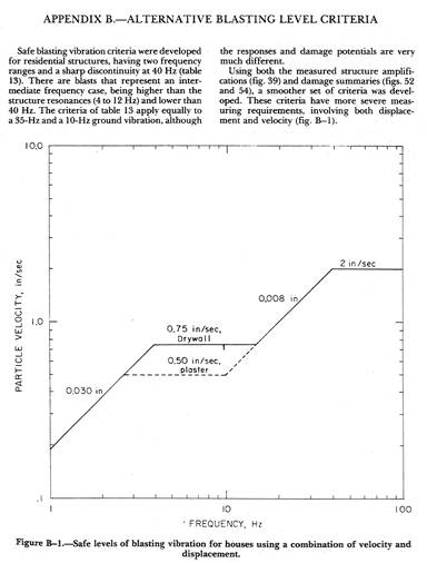
Figure
208.G – Typical Vibration Blasting Criteria
Each blast has a particle
velocity and frequency. The project can
plot these values on the chart in Figure 208.G.
If the point is lower than the plotted line, the blast is within limits
that are generally considered to be safe.
Presplitting (208.09)
Presplitting is a very
effective method of controlling the final appearance of steep slopes; it can
result in a clean sheared face.
Presplitting is required when the slope is steeper than 1H:1V and deeper than 5 feet.
Specialized presplit blasting
explosives are used. Hole
diameters are approximately 3 inches, and the presplit holes are blasted prior
to the production blast. The presplit hole spacing starts at 36 inches. This is adjusted to obtain a good, shear face
of the rock.
Documentation Requirements - 208 Rock Blasting
1. Accept pre-blast survey.
2. Verify the experience of the blasting specialists.
3. Accept and verify the blasting plan.
4. Ensure that the CA-EW-10
Item 208 Blasting Drilling Log is prepared by the driller.
5. Review the blasting area for blasting plan dimensions
with the blasting consultant.
6. Control blasting is used on cut slopes steeper than
1:1 and deeper than 5 feet (1.5 m).
Techniques are outlined in Section 208.10.
7. Production blasting is used for widely spaced
production holes in the main excavation.
8. Review the regulations of explosives as outlined in
Section 107.09.
9. A blasting plan is required at least 2 weeks before
drilling begins.
10. Review the detailed blasting plan of test shots.
11. Document test sections and drilling patterns.
12. Document safety procedures as outlined in 208.08. Ensure that the CA-EW-11
Item 208 Rock Blasting Site Security Plan is prepared by the blaster.
13. Witness all shots.
Inspect all shots using the CA-EW-9
Item 208 Rock Blasting Field Inspection Form.
14. Check vibration, air blast, and flyrock
for all blasts.
15. Check monitoring wells with Hydrologist.
16. Check the presplit face and requirements.
17. Measure presplit areas.
18. Monitor blasting consultants’ hours.
19. Review contractor’s record keeping for explosives and
blasting logs.
20. Review monthly blasting report.
21. Document on the CA-EW-9,
CA-EW-10, CA-EW-11 and the CA-D-2.
Do not repeat information on other forms listed unless necessary.